
Pipe Stress Analysis Explained
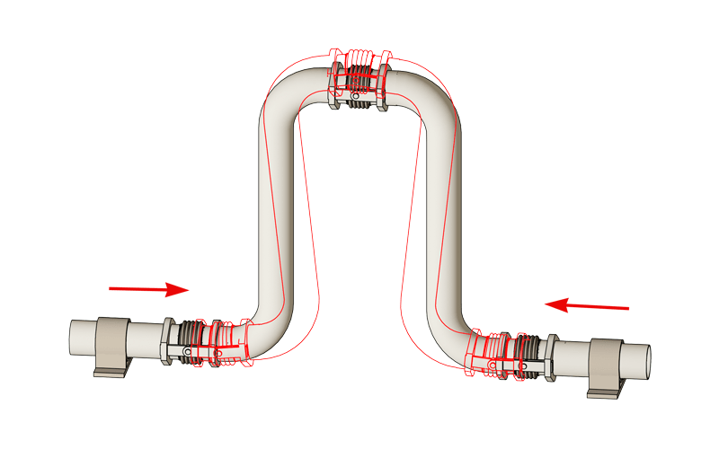
Pipe Stress Analysis The Hidden Science Behind Reliable Piping Systems
Pipe stress analysis blends engineering science with real world judgment. At JSC Engineers we bring this invisible discipline to life ensuring that every pipe system performs safely under pressure temperature and movement.
The Art and Science of Stress Analysis
To most observers pipe stress analysis is invisible until something fails. The need for it becomes clear only when a support breaks a nozzle cracks or a pipe bows under thermal expansion. Behind every reliable piping system is a detailed analysis guided by experience code compliance and design intuition.
In the United States pressure piping design is governed by the ASME B31 series. ASME B31.3 applies to process piping while ASME B31.1 covers power piping. These codes define material limits design stresses and formulas for wall thickness but the practical layout and stress design are left to the system engineer. That is where professional judgment matters most.
When to Perform Pipe Stress Analysis
There is no universal rule but JSC Engineers applies well established criteria to decide when a line requires formal analysis. Conditions that typically trigger a detailed model include:
- Operating temperatures above 150°F for lines 4 inches and larger
- Temperatures above 300°F even for smaller lines
- Connections to rotating equipment heat exchangers or pressure vessels
- Large diameter lines typically above 12 inches
- Cryogenic or hazardous service
- Short anchored hot runs with limited flexibility
- Complex branch systems or lines in seismic regions
A simple screening method sometimes used is the 1500 rule. Multiply the nominal pipe size by the operating temperature in degrees Fahrenheit. If the result exceeds 1500 a formal analysis is generally warranted. For example a 4 inch line at 400°F gives 1600 which indicates that stress analysis is needed.
Why Stress Analysis Matters
- To keep stresses within ASME allowable limits
- To limit nozzle loads on pumps compressors and vessels per API 610 and API 617
- To determine design loads for pipe supports restraints and anchors
- To calculate displacements for interference checks and flexibility
- To improve long term reliability and minimize maintenance
Thermal Expansion and Its Effects
All metals expand when heated and contract when cooled. The coefficient of linear expansion for common materials may appear small but its effect over long runs is substantial. For example one hundred feet of carbon steel pipe can elongate almost one inch for a two hundred degree rise in temperature. If that pipe is restrained at both ends the resulting axial stress can exceed nineteen thousand psi and generate end forces exceeding forty five thousand pounds.
Proper design provides flexibility through loops offsets or spring hangers that absorb movement safely. Without this flexibility the stress can approach yield strength and cause failure of welds supports or connected equipment.
Occasional and Seismic Loads
In addition to thermal conditions piping must withstand occasional loads such as wind snow and seismic events. Seismic analysis uses location specific acceleration factors site classifications and component amplification factors as defined by ASCE and USGS data. JSC Engineers integrates these factors into load cases that combine sustained operating and occasional conditions for a complete design picture.
Design Tools for Stress Relief
- Introduce three dimensional routing with loops or offsets instead of straight runs
- Use expansion joints or slip joints only when space prevents natural flexibility
- Allow sufficient layout space for movement and support accessibility
- Perform stress analysis before fabrication and installation
Expansion joints can solve tight space problems but they also introduce maintenance concerns and high thrust forces. Whenever possible JSC Engineers favors flexibility through routing geometry rather than hardware that requires periodic inspection.
From Model to Reality
At JSC Engineers we use CAESAR II and AutoPIPE for analytical modeling and Revit or AutoCAD Plant 3D for system integration. Our process links the analytical model directly with layout drawings ensuring that pipe routes loops and supports reflect both code compliance and constructability.
The resulting design is not just about code calculations but about how a system behaves when the plant starts up shuts down or experiences upset conditions. Experience remains key because software assists but does not replace engineering judgment.
Conclusion
Pipe stress analysis protects people equipment and long term plant performance. It ensures that every thermal cycle and vibration load is understood and managed. Whether for power generation chemical processing or water treatment facilities JSC Engineers provides the technical depth and practical design skill needed to make complex systems safe dependable and efficient.
Contact JSC Engineers
For assistance with your next piping project contact JSC Engineers or explore our Pipe Stress Analysis Services page to learn more about our capabilities.