
Piping, nozzles & support components
Finite Element Analysis
Look beyond the system model. Evaluate local stresses, deformation, and load transfer in complex piping connections and custom support components.
Contact UsProject analysis: Belinder Pump Station & PEFTF Improvements, Kansas
Local behavior. Documented engineering.
When a beam model is not the whole answer
A piping system model can establish movements and reactions without resolving the local behavior of a nozzle, saddle, clamp, or welded attachment. JSC Engineers provides finite element analysis for those component-level questions, connecting the local model to the actual geometry, loading, and acceptance criteria.
We use FE/Pipe, NozzlePRO, and SolidWorks Simulation as appropriate to the component and scope. Our work connects pipe stress analysis with local evaluation and support design, rather than treating a stress contour as a complete engineering conclusion.
Component-level engineering
Resolve the local load path
Nozzles & branch connections
Evaluate local shell and connection stresses from pressure, forces, and moments, including geometries or load combinations outside the limits of a selected simplified method.
Saddles & pipe attachments
Examine load transfer into the pipe wall at saddles, shoes, trunnions, clips, and welded attachments. Include the attachment stiffness and geometry relevant to the evaluation.
Clamps, cold shoes & custom supports
Evaluate component stresses and deformation under the specified support reactions. Define contact, restraint, and connection assumptions to suit the assembly.
Local stiffness & flexibility
Investigate connection flexibility or stress intensification where needed to improve the relationship between the component model and the overall piping analysis.
Buckling & nonlinear behavior
Scope elastic-plastic, stability, or contact studies when the geometry and loading require more than a linear elastic stress check.
Thermal loading & fatigue
Define a suitable assessment for thermal gradients and repeated loading. Fatigue work requires load ranges, cycles, and appropriate detail assumptions, not just a single operating stress plot.
We establish the governing code, edition, analysis method, and acceptance criteria for the specific component. ASME Section VIII, Division 2, Part 5 methods may be used where applicable; piping and structural components are evaluated against their relevant requirements. Not every model requires every assessment listed here.
An explanation, not just a contour
Understand what the model establishes
A useful FEA report identifies what was modeled, how it was loaded, and how the results were interpreted. We define the required outputs before analysis so the findings can support a design decision or submittal.
Mesh refinement, boundary-condition sensitivity, and comparison with simpler checks are considered where relevant. A local peak stress alone is not automatically a failure, and a low contour value alone does not qualify an entire assembly.
- Analysis basis. Geometry, thicknesses, materials, temperature-dependent properties, load cases, and acceptance criteria.
- Model definition. Element representation, mesh, restraints, contacts, connections, and important idealizations.
- Results & checks. Applicable stress measures, displacements, reactions, and buckling or fatigue results when included in scope.
- Engineering interpretation. Governing locations and cases, limitations, and recommendations for geometry or connection changes.
- Coordinated documentation. A report and marked-up details linking findings to the component drawing and overall load basis.
Start with the engineering question
What to send for an FEA review
Tell us what decision the analysis needs to support: qualifying an attachment, checking an existing component, resolving a submittal comment, or comparing a design change.
Geometry & connection details
Component drawings or CAD, wall thicknesses, weld details, reinforcement, bolting, contact surfaces, corrosion allowances, and available as-built measurements.
Loads & coordinate systems
Forces and moments by load case, pressure, temperatures, thermal gradients, restraint locations, and the directions and reference points used in the system model.
Materials & operating history
Material specifications, operating temperatures, relevant inspection findings, and loading or temperature cycles where fatigue is part of the scope.
Acceptance & submittal requirements
Governing codes, owner criteria, previous calculations, vendor limitations, review comments, schedule, and any required PE sealing.
Discuss your component analysis. We can identify the information needed and coordinate drawing or model transfer after the initial conversation.
Selected component analysis experience
FEA connected to piping and support decisions

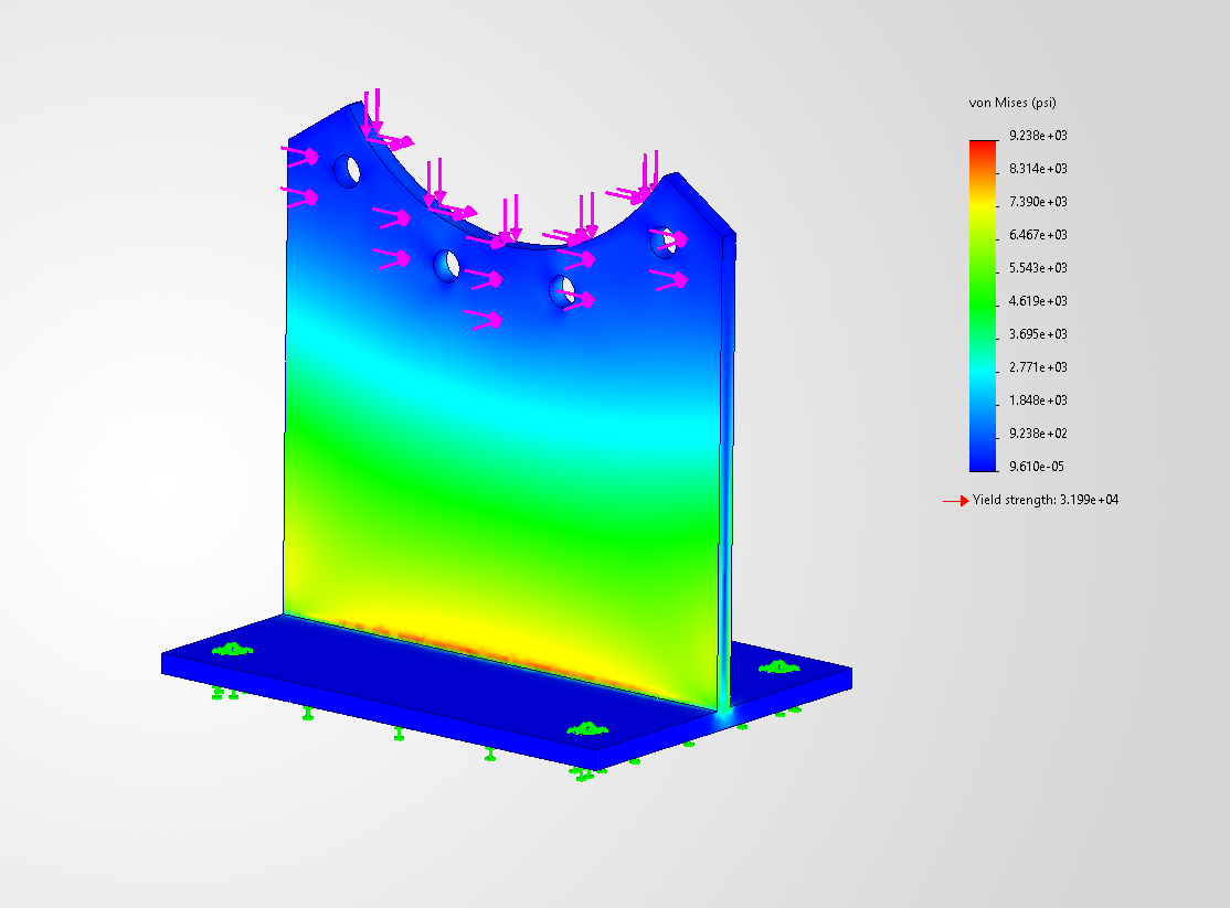
Milestone Reservoir & Pump Station – 42-Inch River Water Pipeline Supports
Local FEPipe evaluation of the governing saddle on a 42-inch river water line under combined vertical, shear, and axial reactions.
View project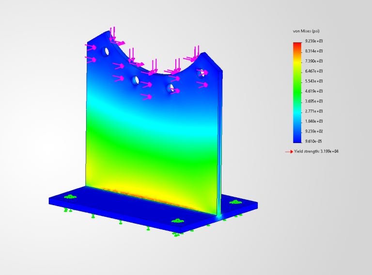
Belinder Pump Station & PEFTF Improvements
Support component analysis coordinated with pipe stress reactions, fabrication details, and concrete anchorage.
View project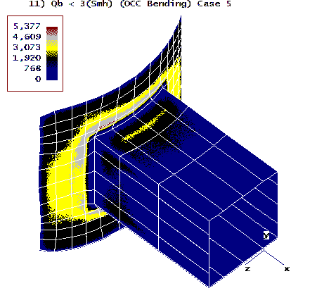
136 East South Temple – High-Rise Riser Stress & Seismic Support Design
NozzlePRO evaluation of local stresses at a custom double-trunnion riser support in Seismic Design Category D.
View projectConnect the engineering scopes
System reactions are the starting point
Component FEA relies on a credible load basis. Where required, we can coordinate the piping model, local component evaluation, and support or anchorage design within one defined scope.
Preliminary calculators cannot establish local attachment acceptance, nozzle adequacy, buckling resistance, or fatigue life.
- Pipe Stress AnalysisEstablish system behavior, restraint reactions, and equipment loads.
- Delegated Pipe Support DesignConnect component findings to framing, details, and anchorage.
- Piping ToolboxExplore preliminary piping inputs before defining the analysis.
Common project questions
Before we start
How is component FEA different from pipe stress analysis?
A pipe stress model generally uses beam elements to evaluate system flexibility, movements, and loads. A local finite element model can resolve shell or solid behavior around a specific connection or component. The two models answer different questions and often need to be coordinated.
Does every nozzle or support need FEA?
No. Suitable code equations, vendor criteria, or established simplified methods may be sufficient. We first consider the geometry, loading, and limits of the available methods before proposing a more detailed model.
Does a red area on a stress plot mean the component fails?
Not by itself. The stress measure, load case, location, mesh behavior, and applicable acceptance criteria must be interpreted together. Local peaks or modeling singularities need engineering review rather than a conclusion based on color alone.
Can JSC review an existing or modified component?
Yes. Provide drawings, verified dimensions and thicknesses, materials, inspection information, and the proposed loading or change. The scope will identify any field verification or additional data needed before a conclusion can be made.
Your next component evaluation
Let's define what the analysis needs to prove.
Send the component, the loading question, and the decision your team needs to make.
Contact Us