
From CAESAR II Loads to Fabrication Drawings: Wastewater Delegated Design
From CAESAR II Loads to Fabrication Drawings: Wastewater Delegated Design
A CAESAR II model does not build a pipe support. It predicts how the modeled piping responds to weight, temperature, pressure, restraints, equipment movements, and occasional loads. The project still needs to translate those results into steel, plates, bolts, clamps, anchors, gaps, and installation instructions.
That translation is the central value of an integrated wastewater delegated design package.
When analysis and detailing are disconnected, the calculation report may show acceptable code stress while the support drawings use different locations or restraint functions. When the workflow is integrated, every meaningful model restraint can be traced to a coordinated support mark and every structural detail can be traced back to a design reaction.
Step 1: Establish the design basis
Before modeling begins, confirm the governing criteria and system data. For wastewater piping, that often includes:
- Pipe size, wall, material, lining, joint type, and manufacturer
- Design and operating pressure and temperature
- Empty, operating, test, and flooded weights
- Valve, actuator, meter, and inline equipment weights
- Pump, blower, tank, and equipment connection data
- Piping-code edition and owner specifications
- Seismic, wind, settlement, hydraulic transient, and other project loads
- Equipment allowable nozzle loads
- Structural attachment locations and restrictions
The model is only as defensible as these inputs. A default friction coefficient, assumed valve weight, or idealized equipment anchor can materially change support reactions.
Step 2: Define model boundaries
Model boundaries should represent real stiffness and restraint. A wastewater system may terminate at a pump nozzle, tank wall, buried transition, building penetration, flexible coupling, or a section of piping analyzed by another party.
At each boundary, document what movement and rotation are permitted. For example, a wall penetration is not automatically a six-direction anchor. A mechanical coupling is not automatically a hinge. A buried transition cannot be modeled accurately without a rational representation of soil or restraint conditions when those effects matter.
Good model plots label the boundary conditions so the reviewer can compare them with equipment drawings and the coordinated piping model.
Step 3: Develop the support philosophy
The first support layout should reflect both the pipe material and the system's intended movement.
- Rests and hangers carry vertical weight.
- Guides control lateral movement while allowing movement in an intended direction.
- Line stops limit axial travel at defined points.
- Hold-downs prevent uplift while permitting other movement as detailed.
- Anchors restrain defined translations and rotations and can create large reactions.
- Springs support vertical load while accommodating calculated vertical movement.
The support philosophy should avoid over-restraint. Adding restraints can reduce local displacement but increase thermal forces, nozzle loads, and reactions elsewhere. The objective is controlled flexibility, not maximum rigidity.
Step 4: Build meaningful load cases
The engineer combines basic loads into analysis cases that represent design conditions. Exact combinations depend on the governing code and project criteria, but the workflow commonly considers:
- Installed or empty condition
- Sustained operating weight and pressure
- One or more operating temperature cases
- Thermal expansion ranges
- Seismic or wind directions
- Test condition
- Settlement or imposed anchor movement
- Hydraulic transient forces when separately defined
The analysis should distinguish cases used for piping-code compliance from cases used to design supports and check equipment. A support frame may be governed by an operating reaction or occasional load even when a different combination controls code stress.
Step 5: Review behavior, not just pass/fail ratios
Software compliance output is one part of engineering review. The analyst should also ask:
- Does the deflected shape make physical sense?
- Is thermal growth moving toward the intended flexible leg or loop?
- Are any guides lifting off or binding?
- Do friction assumptions produce unstable or unrealistic behavior?
- Are equipment nozzle forces and moments acceptable?
- Are support reactions practical for the available structure?
- Do large changes between cold and operating load indicate the need for a spring?
- Will gaps remain functional after installation tolerances are considered?
This behavioral review often identifies a better support arrangement before steel is detailed.
Step 6: Create a reaction envelope that designers can use
CAESAR II may report many force and moment components for many load cases. The support designer needs a clear, conservative, and traceable set of demands.
For each support, the reaction schedule should identify:
- Support mark and model node
- Coordinate system and sign convention
- Vertical, lateral, and longitudinal forces
- Moments where transferred by the detail
- Governing load case or a clearly defined envelope
- Calculated movement and direction
- Friction or gap assumptions
- Any load amplification or design factor applied outside the piping model
Avoid combining maxima that cannot occur together unless the support is intentionally designed for a conservative absolute envelope. If a reaction set is concurrent, label it as concurrent. If it is an independent component envelope, say so.
Step 7: Design the structural load path
The support reaction moves through several components: pipe attachment, support member, connection, anchor, and receiving structure. Each link needs compatible assumptions.
For a typical bracket or frame, calculations may cover:
- Local effects at the pipe attachment
- Bending, shear, axial load, torsion, and interaction in support members
- Plate bending and local yielding
- Weld-group forces
- Bolt tension, shear, bearing, and slip where relevant
- Base plate and anchor behavior
- Concrete edge distance, embedment, and anchor-group effects
- Deflection and serviceability
- Stability and bracing
If the primary structure stays in the EOR's scope, issue reactions and connection locations early enough for review. A support is not coordinated if its base plate is adequate but the existing beam beneath it is unknown.
Step 8: Produce fabrication-ready details
The drawings should communicate the analytical intent without requiring the fabricator to interpret the stress model. Each support mark needs dimensions, member sizes, materials, connection details, coating or finish, pipe interface, and installation notes.
Show directional behavior graphically. Indicate sliding surfaces and gaps. Identify whether bolts are snug-tight or pretensioned when that matters. State restrictions on field welding and drilling. For FRP, ductile iron, lined pipe, and stainless steel, include the material-specific contact and attachment requirements.
The design should also consider fabrication tolerance, erection access, wrench clearance, insulation, maintenance, and the sequence used to set the pipe at its cold condition.
Step 9: Run a model-to-drawing consistency check
Before submittal, compare the latest analysis and drawing set support by support:
| Check | Question |
|---|---|
| Location | Is the drawn support at the modeled point? |
| Function | Does the detail restrain the same directions as the model? |
| Gap | Is the modeled gap shown on the drawing? |
| Movement | Does the shoe, slide, or spring have adequate travel? |
| Load | Does the structural calculation use the current reaction? |
| Interface | Has the receiving-structure reaction been issued? |
| Material | Is the pipe contact detail compatible with the supplied pipe? |
This is one of the highest-value quality-control steps in delegated design.
Step 10: Manage comments as engineering changes
Not every review comment is a drafting revision. Moving a restraint, changing a support function, or reducing a gap may require the pipe model to be rerun. Maintain a comment log and classify each response as clarification, drawing revision, support recalculation, or full model-impact review.
Similarly, field deviations should be evaluated before they are accepted. A few inches of relocation may be irrelevant at a long gravity span but significant near an anchor, nozzle, expansion joint, or equipment connection.
What the owner and contractor receive
An integrated package gives the project one coordinated chain:
Design basis → pipe stress model → support reactions and movements → structural calculations → support schedule and details → reviewed installation.
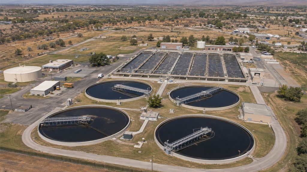
On JSC Engineering's Niwot wastewater treatment plant work, the delegated scope connected CAESAR II analysis with support loads, custom restraints, and structural support design for treatment-process piping. That type of continuity helps reduce the gap between code-compliant analysis and constructible field work.
JSC's delegated design piping team can develop the full chain or coordinate with analysis and structural information supplied by others. To scope the work, provide current piping geometry, system conditions, specifications, structural backgrounds, and the required construction-release sequence.