
Power Plant Pipe Stress: Where B31.1 and B31.3 Apply
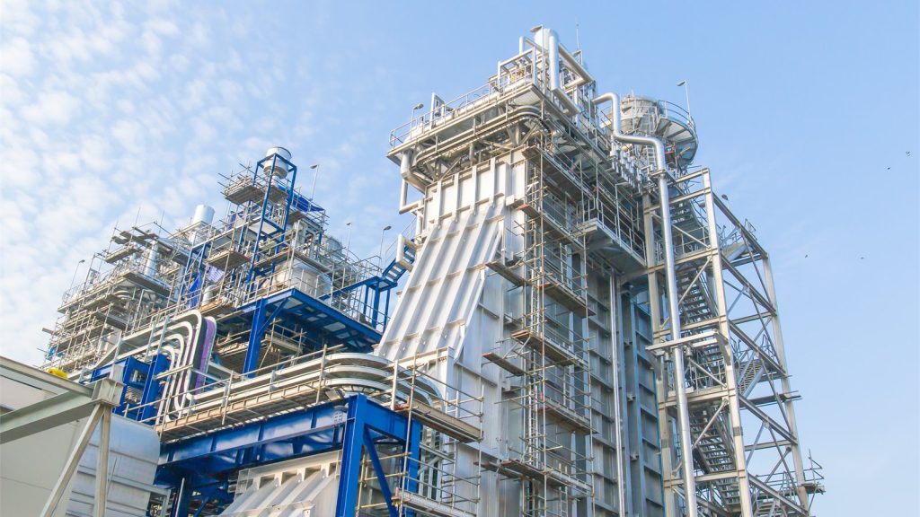
Power Plant Pipe Stress: Where B31.1 and B31.3 Apply
Power plants are not always governed by one piping code. ASME B31.1 covers power piping systems typically found in electric generating stations and certain other plants. ASME B31.3 covers process piping typically found in refineries, chemical and related processing facilities. Depending on plant type and system function, both may appear on the same project.
The correct question is not “Which code applies to this facility?” It is “Which code applies to this piping system, and where is the boundary?”
That boundary affects material rules, design requirements, stress evaluation, examination, testing, documentation, and the assumptions used in a pipe stress model. It should be established by the owner and engineer of record before analysis begins.
What B31.1 covers
ASME describes B31.1 as covering piping systems typically found in electric power generating stations, industrial and institutional plants, geothermal heating systems, and central or district heating and cooling systems. It also addresses boiler-external piping within its defined relationship to the ASME Boiler and Pressure Vessel Code.
In a power-generating facility, systems commonly assigned to B31.1 may include portions of steam, feedwater, condensate, and other power-cycle piping. The actual classification depends on code scope, contract documents, equipment boundaries, and project-specific definitions.
High temperatures, high pressures, large movements, thick-wall components, and frequent cycles make flexibility and support behavior especially important in many B31.1 systems.
What B31.3 covers
ASME B31.3 applies to process piping typically found in petroleum refineries, chemical, pharmaceutical, semiconductor, cryogenic, and related processing plants and terminals. Power facilities may contain auxiliary systems that the owner classifies under B31.3 because of their process function.
Examples might include certain chemical dosing, fuel treatment, gas processing, emissions-control reagent, water-treatment, or packaged process systems. These are illustrations only. A system name does not assign its code; the documented project basis does.
A plant can have several code jurisdictions
A combined-cycle plant may include:
- Boiler and boiler-external piping governed by the applicable BPVC/B31.1 boundary
- Main steam, reheat, feedwater, and condensate systems assigned to B31.1
- Gas or liquid fuel systems potentially governed by another B31 section or regulation
- Chemical, water-treatment, or emissions-control process systems assigned to B31.3
- Building plumbing, fire protection, or refrigerant systems governed by other codes
- Vendor skids designed to specified standards with defined battery limits
The code map should be captured in the line list, P&IDs, system specifications, and stress-analysis index. Do not wait for the final report to discover that two connected segments were modeled under inconsistent rules.
Define the code boundary physically
A code boundary should correspond to an identifiable location such as a valve, equipment nozzle, weld, flange, or other defined terminal. The drawings and line list should state which side belongs to which system.
At the boundary, coordinate:
- Design pressure and temperature
- Material and component specifications
- Wall-thickness basis
- Examination and testing requirements
- Stress-analysis assumptions
- Equipment and structural loads
- Documentation and turnover responsibility
If two systems designed under different B31 sections are connected, the interface still needs a compatible mechanical design. Code labels do not make displacement and force disappear at the battery limit.
Stress-analysis differences matter
B31.1 and B31.3 share a common engineering foundation, but they are separate codes with different scope language, rules, equations, allowable stresses, stress indices or intensification treatment, load categories, and documentation requirements.
The analyst should use the correct code edition and software implementation for each model. Where a model crosses a code boundary, it may be clearer to create coordinated submodels with common boundary forces and movements. If one combined model is used, the report should explain how code compliance is evaluated for each segment.
Never assume that a line passing under one code would automatically pass the other. Likewise, do not present percentage utilization from two codes as if the values are directly comparable without explaining their different bases.
Support design does not stop at code stress
A code-compliant pipe can still impose unacceptable loads on a turbine, pump, HRSG connection, structure, or support component. Power plant analysis should also evaluate:
- Nozzle forces and moments using vendor or project allowables
- Cold and operating support loads
- Vertical movement and spring selection
- Support lift-off
- Friction at sliding supports
- Guide, stop, and anchor reactions
- Thermal movement through penetrations and around equipment
- Seismic, wind, steam hammer, relief, and other occasional events as applicable
- Fatigue and cycling demands for frequently started units
The support arrangement should carry weight while allowing controlled movement. Large hot lines often use variable or constant spring hangers where rigid supports would unload or restrain vertical travel. Learn more about spring hanger design.
HRSG piping requires system-by-system coordination
An HRSG connects combustion-turbine exhaust heat to the steam cycle and contains many systems with different temperatures, pressures, diameters, equipment interfaces, and operating modes. Main steam or superheater piping may see large thermal movements, while smaller drains, vents, chemical injection, or auxiliary lines may have different code assignments and transient concerns.
The model should consider startup, normal operation, shutdown, bypass, and other credible modes defined by the plant. Equipment and vendor movements should be coordinated with drum, header, module, turbine, and skid design.
JSC Engineering's HRSG pipe stress project in Ontario, California used an ASME B31.1 basis for systems including feedwater and superheater piping, along with related smaller-bore systems. The work addressed thermal and pressure effects, equipment connections, support selection, layout, and qualification.
Cycling and flexible operation
Plants that start, stop, or change load frequently can accumulate more damaging cycles than a unit operating steadily. The project should define anticipated operating cycles and temperature ranges rather than treating only the maximum temperature as controlling.
Potential issues include:
- Repeated movement at branch connections and terminal points
- Support friction and stick-slip behavior
- Springs traveling through a wide range
- High nozzle loads during intermediate operating states
- Condensate and two-phase flow events
- Temporary load during startup or drain operation
- Thermal stratification or differential temperature where credible
The appropriate fatigue or cyclic evaluation depends on the governing code and project requirements.
Dynamic events need defined forcing loads
Steam hammer, water hammer, safety-valve reaction, turbine trip, vibration, and seismic events are not interchangeable. A credible analysis requires the event's location, magnitude, direction, time behavior, and applicable combinations.
A process or transient specialist may determine hydraulic forces. The pipe stress engineer then evaluates piping response and designs restraints appropriate to the event. Snubbers and struts may resist rapid movement while allowing slow thermal travel, but their actual stiffness, clearances, and attachment loads must be included.
Build a code-jurisdiction matrix before modeling
A practical matrix includes:
| Field | Purpose |
|---|---|
| Line or system number | Identifies the analyzed segment |
| Service and equipment | Explains system function |
| Governing code and edition | Establishes the compliance basis |
| Code boundary | Identifies the physical terminal |
| Design/operating cases | Defines pressure and temperature states |
| Owner specification | Captures requirements beyond the code |
| Vendor criteria | Defines equipment limits and movements |
| Analysis package | Assigns the correct model and responsible engineer |
Review the matrix with the mechanical EOR, owner, boiler/equipment suppliers, and other affected disciplines before final model development.
What an effective power plant pipe stress report includes
- Code-jurisdiction and model-boundary definition
- Applicable editions and owner criteria
- Operating modes and load cases
- Piping-code stress summaries by system
- Equipment nozzle-load evaluations
- Calculated movements and spring travel
- Support reactions for structural design
- Dynamic or occasional load basis where included
- Required support modifications and installation settings
- Assumptions requiring vendor or field confirmation
JSC Engineering provides power plant pipe stress engineering under B31.1, B31.3, and other project-defined standards. Send the line list, P&IDs, code matrix, operating cases, equipment data, and support information to establish the correct analysis boundaries.
Frequently asked questions
Is all piping inside a power plant B31.1?
No. B31.1 applies to systems within its scope, but a power plant may contain piping governed by B31.3, other ASME B31 sections, building codes, fire codes, or vendor requirements.
Can B31.1 and B31.3 be used in one stress model?
Analysis software may support both, but the report must evaluate each piping segment under its governing code and clearly define the interface. Separate coordinated models are often easier to audit.
Does B31.1 determine spring-hanger size?
The code and project criteria inform the design, while spring selection uses calculated loads, travel, variability limits, space, and hardware requirements. The stress model and final spring schedule must agree.